Computer Vision Portfolio
2023-01-23
Table of contents
- Introduction
- Problem statements
- Use case 1
- Use case 2
- Use case 3
- Methodology and process
- Use case 1
- Use case 2
- Use case 3
- Results and final evaluation
- Use case 1
- Use case 2
- Use case 3
- Appendix
Introduction
This text showcases three use cases for computer vision. For these use cases, multiple methods have been used. These methods include preprocessing, edge detection, contour detection, shape matching, filtering, and circle detection.
The code used for this project can be found using this link to the Gitlab repository.
Problem statements
Use case 1: Integrated circuit package recognition
There are many different integrated circuit (IC) package types and sizes. Some are similar in size and shape but with different amounts of pins. Others are completely different. Being able to check whether or not an IC has the same package size as expected could be useful in a PCB assembly factory with pick-and-place machines.
It is possible to determine the specific package type of an integrated circuit?
Use case 2: Colour detection of pool balls
The second use case looks at detecting colours of pool balls.
Use case 3: Tracking of pool balls
Tracking pool balls in videos.
Methodology and process
Use case 1
This first use case involves finding the right IC package type(s) in a given image.
Reference images
to find the right IC package type(s) in a given image the first step was getting great images that could be used as references. Getting the right reference images was more difficult than expected. This was because the pins would reflect the light around them and blend in, making edge detections difficult.
| SO8 | SO16 | SOT23-3 |
|---|---|---|
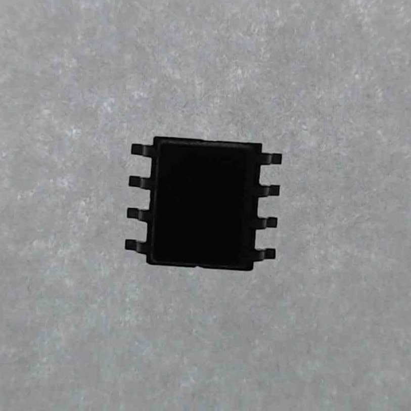 | 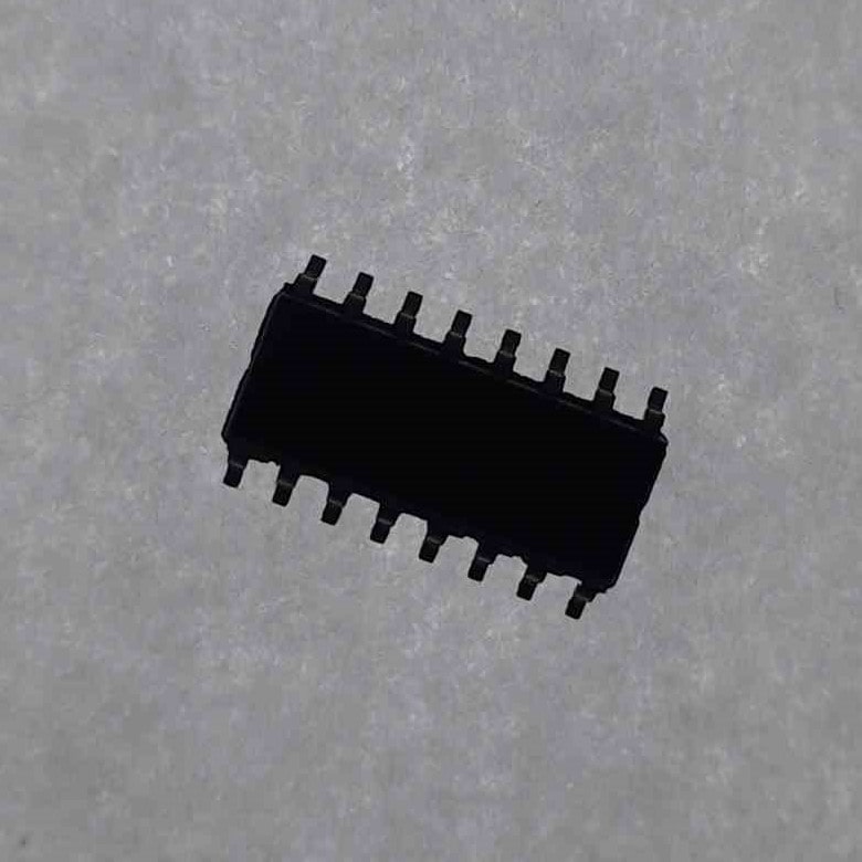 | 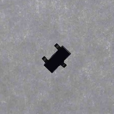 |
The table above shows cropped images of the different ICs. These images are captured with a light source directly behind them. This results in high contrast on both the body and the pins of the ICs.
Contour detection
These reference images are preprocessed Gaussian blur with a kernel size of 7 by 7. Using a smaller kernel size like 3 by 3 resulted in found contours on the background.
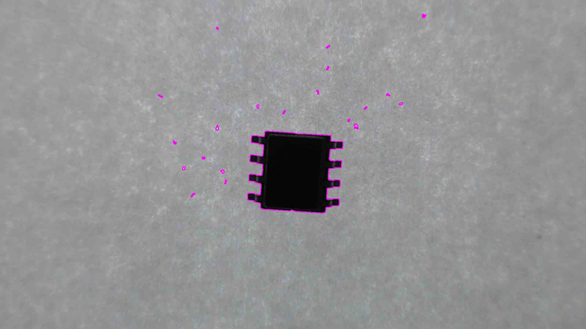
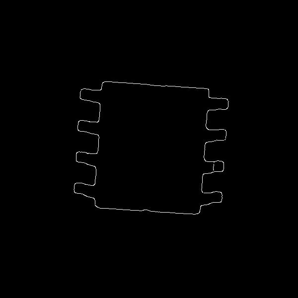
Canny edge detection is used on the blurred image with thresholds of 50 and 100. This results in the image below.
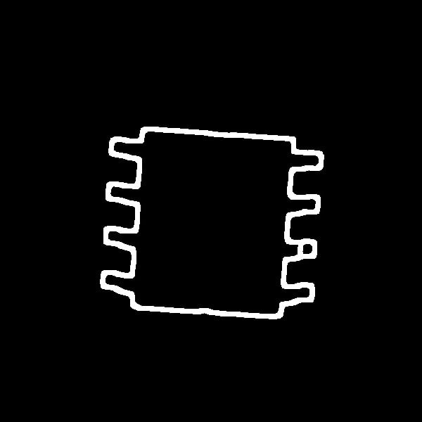
When inspecting the edge up close some small gaps can be seen. To enclose the shape completely the edge was dilated with a 7 by 7 kernel, as shown below.
| Edge | Dilated |
|---|---|
 |  |
Finding the external contour of the dilated image using the findContours() function gave de result shown below.
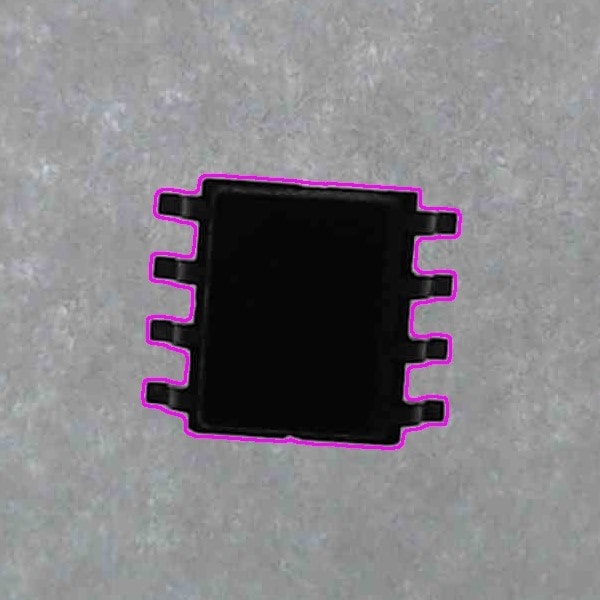
To get the contour of all three of the reference images a for loop was used. This for loop (shown below) iterates for the number of reference images, preprocesses the images the methods explained earlier, and stores the contours in a vector.
for (int IC = 0; IC < number_of_reference_img; IC++) {
	cvtColor(ICs_src[IC], imgGray, COLOR_BGR2GRAY);
	GaussianBlur(imgGray, imgBlur, Size(7, 7), 3, 0);
	Canny(imgBlur, edges, 50, 100);
	dilate(edges, dilated, kernel);

	contour_src[IC] = extractContours(dilated);
}
The result of this for loop is shown below.
| SO8 | SO16 | SOT23-3 |
|---|---|---|
 | 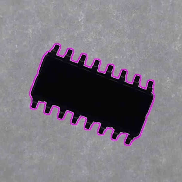 | 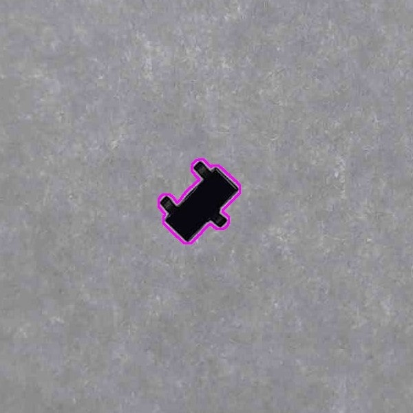 |
These images show one contour that enclosed the reference images. These contours are used to find the best match.
Matching contours
Finding the best match is done by comparing the contour of the reference images to a contour found on a target image. Comparing the contours is accomplished using matchShapes(). This function returns a value of how dissimilar the two contours are. A value of 0 represents that two contours are the same. This means that when comparing the reference images to a target image the match with the lowest value is the most likely match.
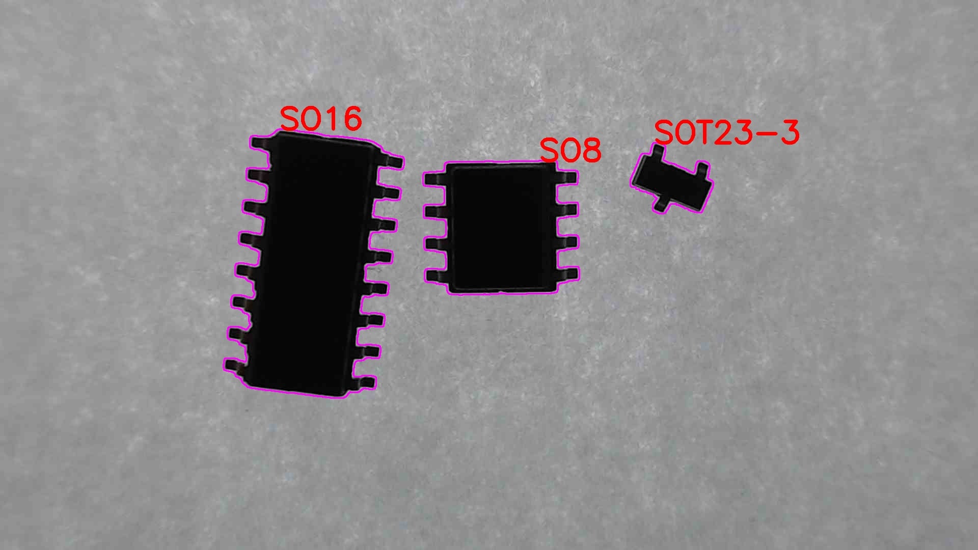
The target picture has gone through the same preprocessing as the reference images. The output is shown below. Other output images can be viewed in the appendix.
Use case 2
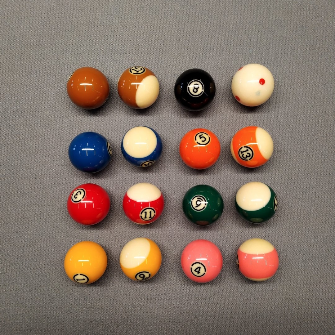
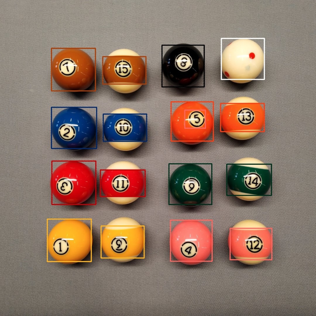
Finding the different colours in the image below was accomplished using masks with minimum and maximum thresholds. This mask also resulted in some false positives. These were removed by filtering out contours smaller than a given size.
Thresholds and masks
Creating a mask for all the different colours was achieved using the inRange() function. The source image is converted to HSV and the lower and upper thresholds apply. This resulted in masks that would in most cases, like the red below, only show the two balls of each colour.
| Red mask | Brown mask | Cue ball mask |
|---|---|---|
 |  |  |
However in other cases as the brown and cue ball it was not possible to perfectly mask out everything else. But there was a decent size difference.
Contour size
This size difference was used by finding all the contours and filtering out the contours below a size of 23000. Finding the contours was accomplished with Canny edge detection when dilating the image and then extracting the contours.
Below is shown the edges found with Canny with thresholds of 50 and 100. All images with edges for all the different colours can be found in appendix.
| Red edge | Brown edge | Cue ball edge |
|---|---|---|
 |  |  |
The edges were dilated with a kernel size of 7 by 7. All images with dilated edges for all the different colours can be found in appendix.
| Red dilated | Brown dilated | Cue ball dilated |
|---|---|---|
 |  |  |
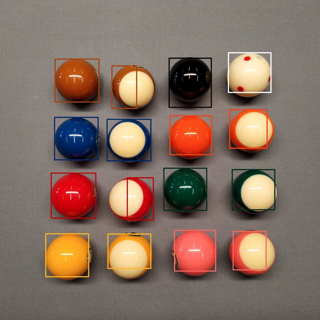
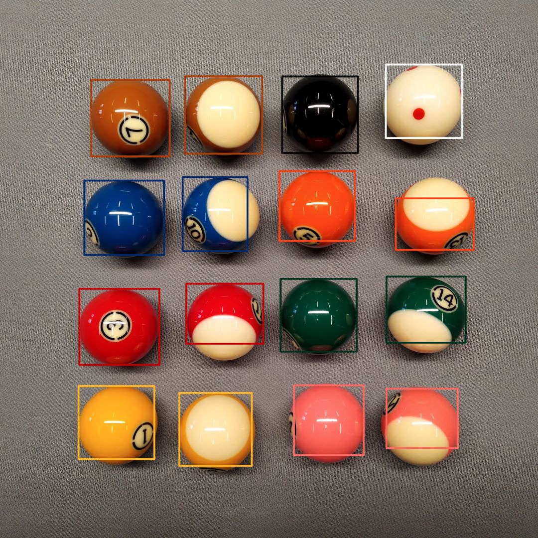
Finding the lower area limit by inspecting the contour sizes visually, gave a size of 23000 for the coloured balls and 112000 for the cue ball. Drawing a rectangle around the contours within these parameters gets the result shown below.
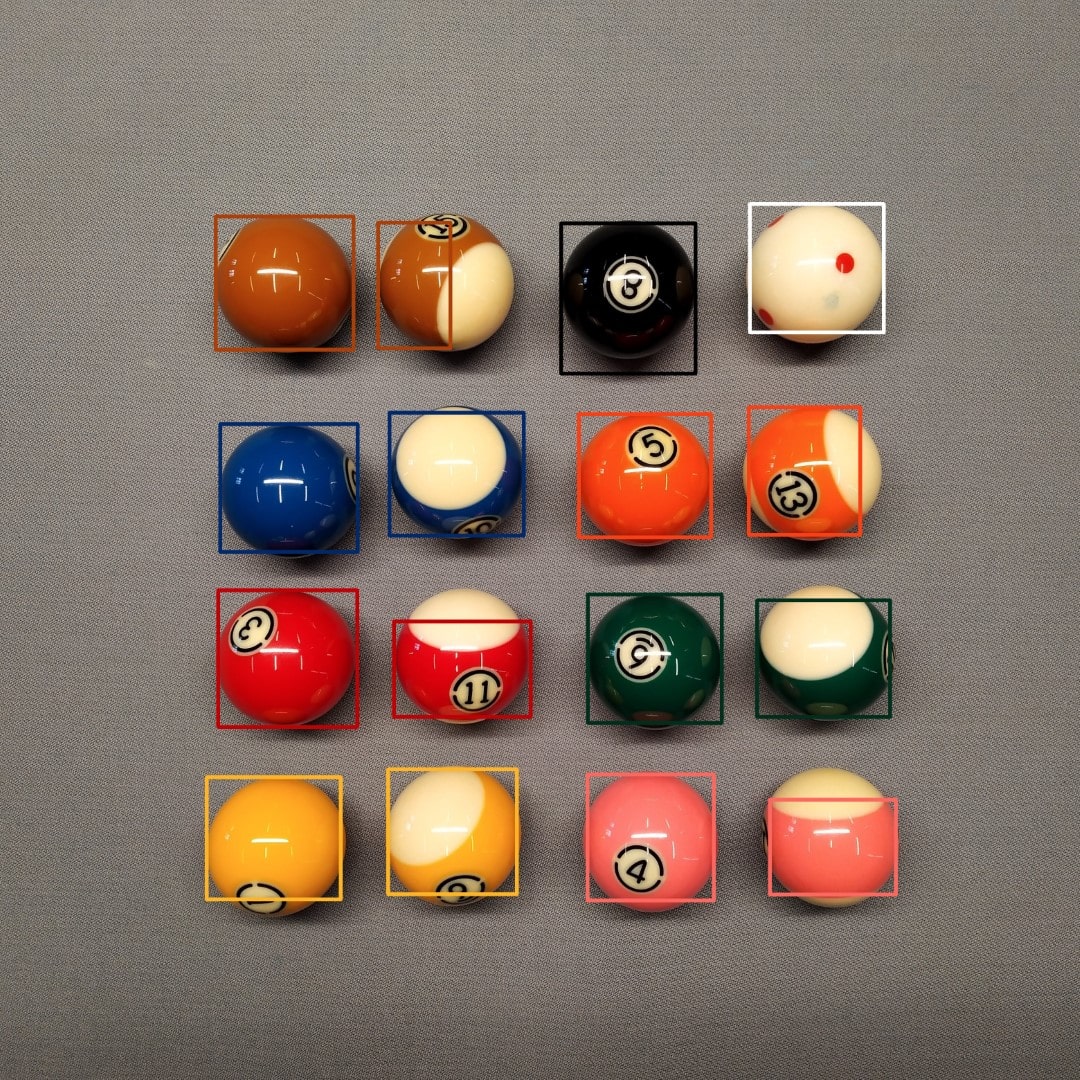
More output images can be seen in the appendix.
Use case 3
Tracking the ball in a video is accomplished by first blurring and edge detecting to remove the gray fabric. After that using the HoughCircles() function to detect the balls.
The pictures in the table below show the original frame and to the right the image after blurring and Canny edge detection.
| Original Frame | Edge detection |
|---|---|
Circle detection
Detection circles are done with the HoughCircles() function shown below. The parameters are critical for correct circle detection and took some time to get correct.
HoughCircles(edges, circles, HOUGH_GRADIENT, 1, imgBlur.rows / 64, 1, 10, 10, 15);
The images below show two frames from the video where all the balls were detected.
| Frame 1 | Frame 2 |
|---|---|
The videos can be viewed here:
Results and evaluation
Use case 1
As seen in the IC output image the three ICs are labelled correctly. Each contour has been compared with each of the three reference images. This was possible because of multiple reasons.
Firstly and most importantly the images have a high contrast to the background on both the body and the pins of the IC. This greatly aided in successfully blurring out the background only. In other lighting conditions, the pins would reflect the light and blend into the background. This resulted in detached pins when edge detecting.
With the high-contrast image Canny edge detection found the edge with no false positives. The dilation with a kernel size of 7 by 7 was because it gave the best results when matching shapes.
The biggest problem with the current program is that it will match the reference image to any object if the score is less than one. This means that if an IC not included in the reference set was used as a target image it would probably still be recognised as one of the ICs in the reference set. This adds another complication that all ICs should be able to detect needs to be in the reference set.
Use case 2
Detecting colours on pool balls does work with the explained methods. On the four images processed only one false positive was found.
However it only works in this specific lighting condition, and only with pool balls in the same colour. In different lighting conditions, the colour might not be in the thresholds used to mask every colour. The program also does not work on different size images or if the picture is captured at a different distance from the table. This is due to the limit of the contour area. The limit is the number of pixels. If the size of the image were to change the contour area sizes would most likely fall out of bounds. This could possibly be solved by using a circle detector to find the balls, calculate an average area and then use this area as a reference to the limits.
Another way would be to find the contours of the balls, then find the most and second most frequent colour inside the contour. The ratio between these colour would determine both the colour but also if the balls were solid or striped.
Use case 3
Tracking pool balls in a video was accomplished quite well. The 8-ball brake has a few false positives near the pockets. The 9-ball break has the same false positive but also some false positives near the magic rack. The circle detection is also very shaky but this might just be due to the handheld camera. Very fast-moving balls have an oblong shape and will not be detected. Solving this would require a high frame rate camera.
Appendix
Use case 1 outputs
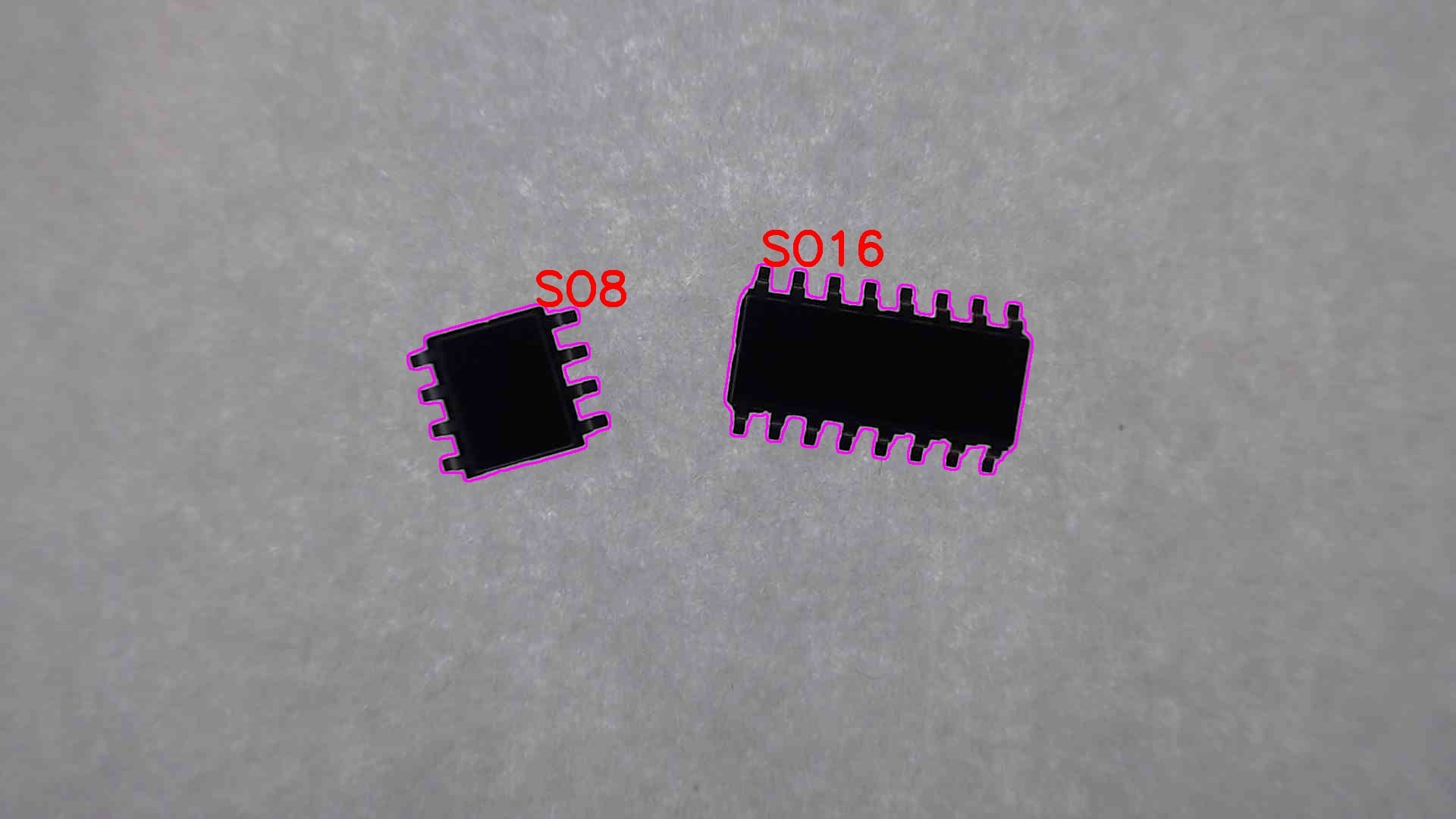
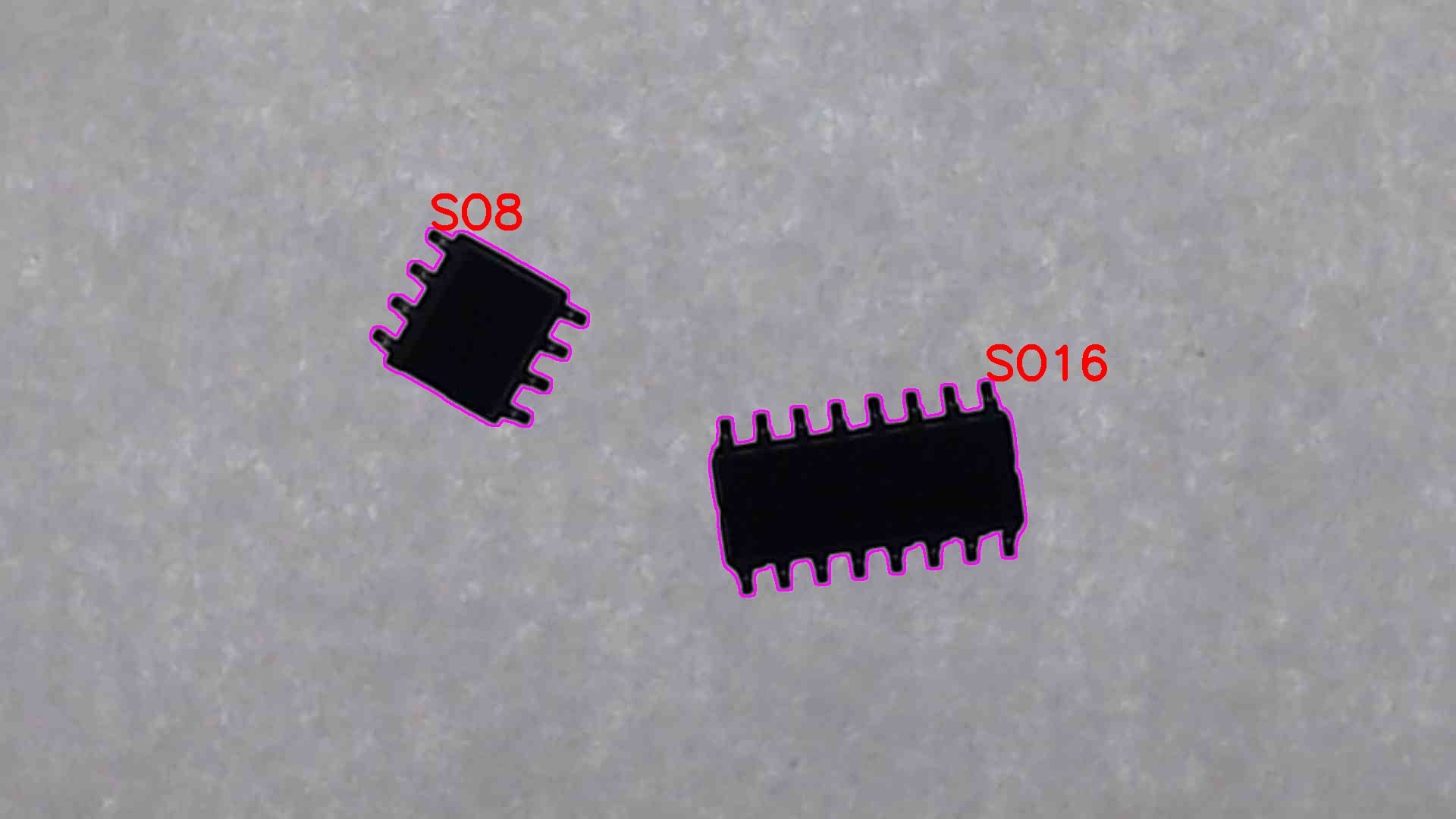
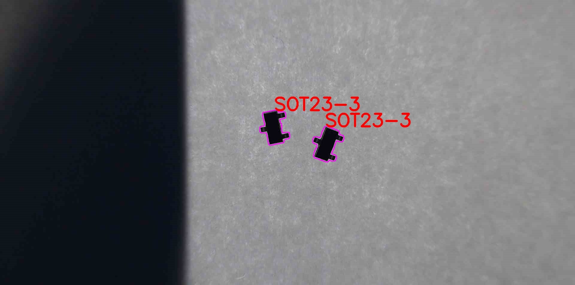
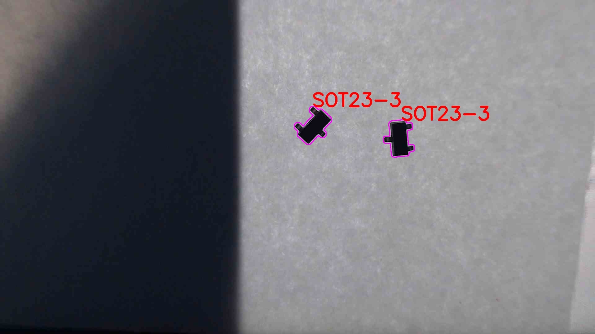
Use case 2
Masks
| Brown mask | 8 ball mask | Cue ball mask |
|---|---|---|
 |  |  |
| Blue mask | Orange mask | Red mask |
 |  |  |
| Green mask | Yellow mask | Pink mask |
 |  |  |
Canny
| Brown canny | 8 ball canny | Cue ball canny |
|---|---|---|
 |  |  |
| Blue canny | Orange canny | Red canny |
 |  |  |
| Green canny | Yellow canny | Pink canny |
 |  |  |
Dilated
| Brown dilated | 8 ball dilated | Cue ball dilated |
|---|---|---|
 |  |  |
| Blue dilated | Orange dilated | Red dilated |
 |  |  |
| Green dilated | Yellow dilated | Pink dilated |
 |  |  |
Output
| Output 0 | Output 1 |
|---|---|
 |  |
| Output 2 | Output 3 |
 |  |