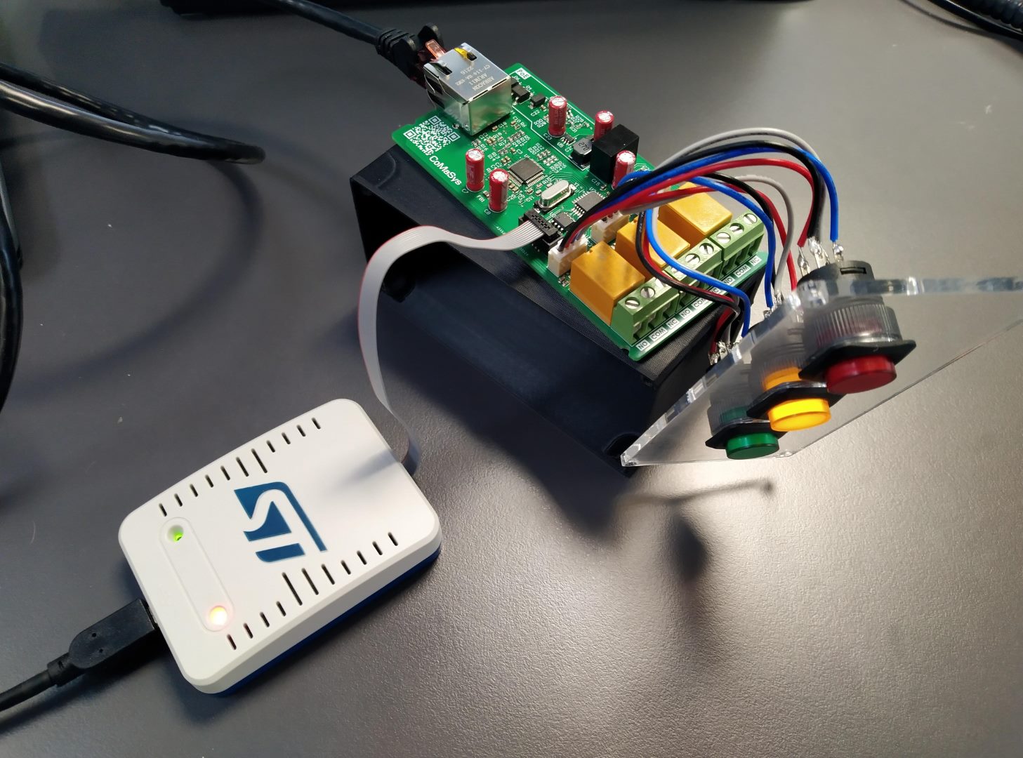
Power over Ethernet STM32
2023-07-03
Introduction
For my final exam project I designed and developed an Internet of Things (IoT) device with Power over Ethernet. This text shows an overview of the project. The device has been developed in collaboration with CoMaSys ApS. CoMaSys has handled everything serverside.
Solution Overview
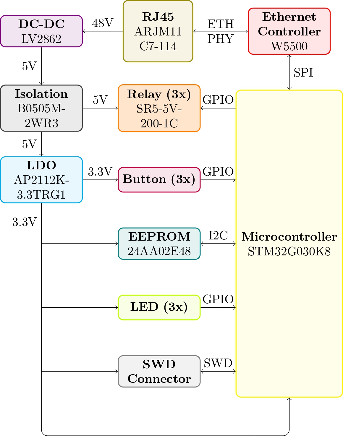
The device consists of many different components and Integrated Circuits (IC) on a Printed Circuit Board (PCB). The main and most important components are displayed in the high-level system block diagram shown in the block diagram. The block diagram shows the component type in bold and the manufacturer part number underneath.

The first action the user needs to do is to insert an RJ45 Ethernet cable into the RJ45 connector. The Ethernet cable needs to be connected to a PoE (Power Over Ethernet) injector or switch. PoE is used to supply the device with power. The voltage of PoE is typically 48 V. The 48 V is converted down to 5 V using a switching DC to DC converter. This supplies a 5 V to 5 V DC converter with isolation. The isolation is required as per the PoE standard. This isolated converter supplies the rest of the system with power, resulting in a completely isolated device. The 5 V is used to activate the three relays and supply a Low Dropout Regulator (LDO). The LDO converts the 5 V to 3.3V and supplies power to the microcontroller, EEPROM, three LEDs, Three buttons, and Ethernet Controller.
The microcontroller is an STM32, it controls all devices on the PCB. It activates the relays, reads if the button is pressed, reads a MAC address off of the EEPROM, and activates the LEDs. The microcontroller is programmed in C++ using the Arduino core.

Functionality
When the device is powered it will, with a given interval, continuously request data from a database using HTTP. The request includes a query of a unique MAC address used to identify devices. The response the device gets to the HTTP request determines the interval and state of the LEDs and Relays.
When a pushbutton is pressed the device also makes a HTTP request. This request also includes a query of the MAC address, and also a query of which button was pressed. The server changes the data in the database corresponding to what button was pressed. The server then responds with the data that was just changed. The relays and buttons are set accordingly.
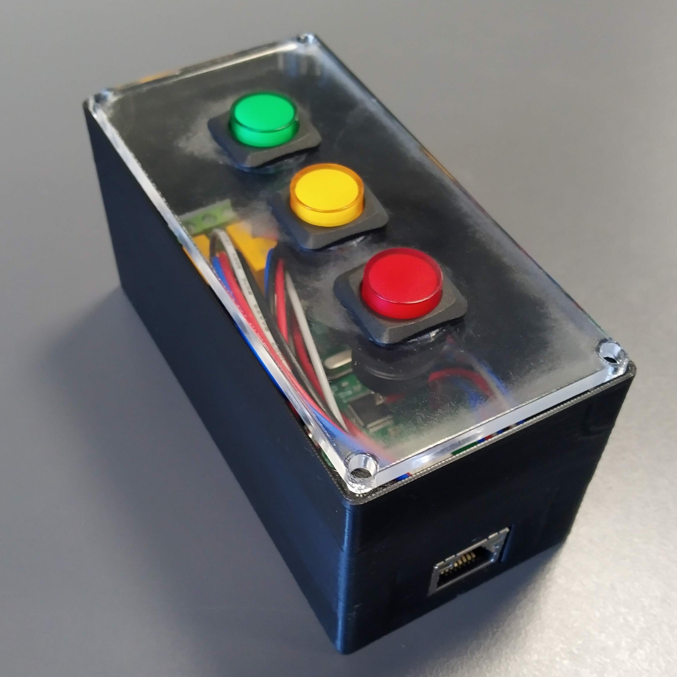
The picture below shows the PCB and buttons assembled in a case.

Hardware layout
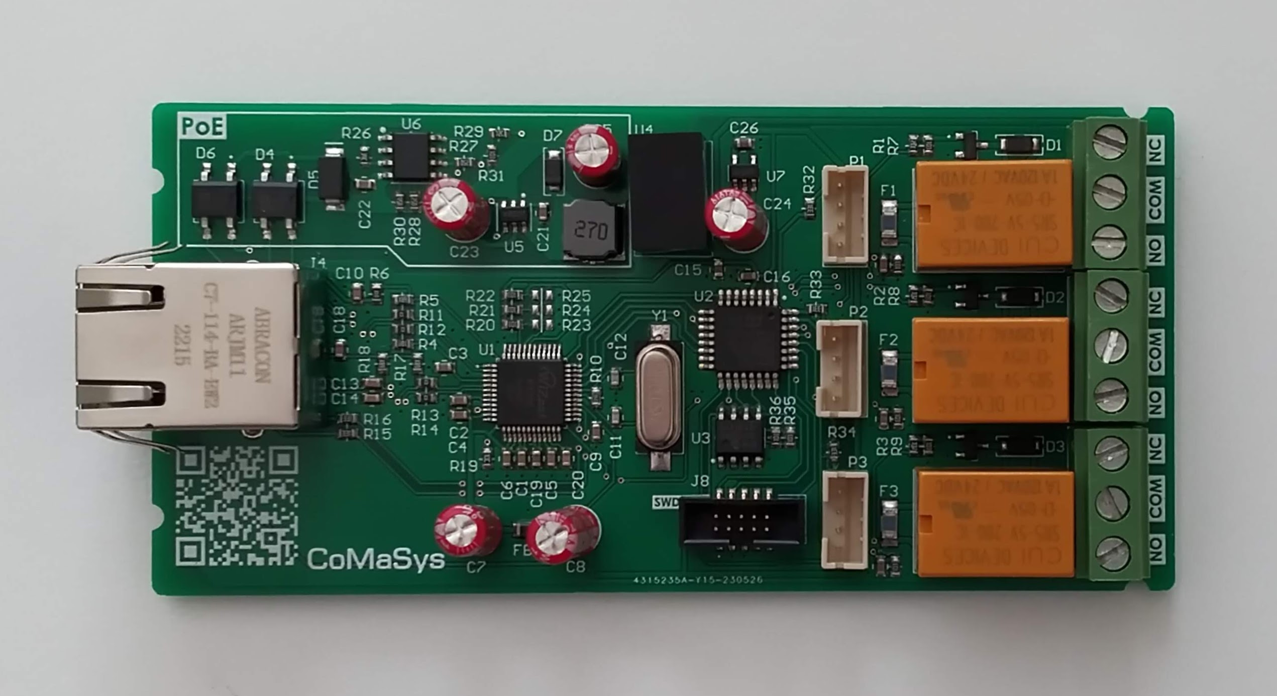
The schematic and hardware layout are made using Altium Designer. The figure should be viewed in combination with the assembly view and the Bill of Material.
